




Automatic Sliding Door Dimensions: What to Measure Before Ordering
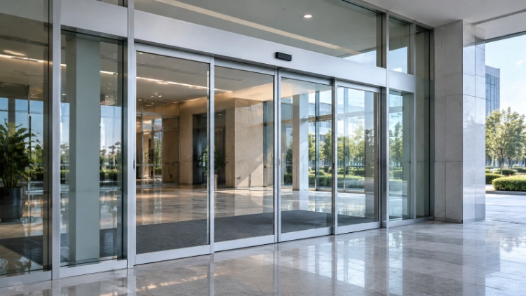
An automatic glass entrance can fit neatly within an architectural elevation yet fail to provide the passage width that the building needs. The structural opening, finished opening, moving glass leaves, fixed sidelites, and operator housing are different dimensions. If a quotation uses one number for all of them, the resulting door may have insufficient travel, an awkward header connection, or a narrower clear passage than expected.
Automatic sliding glass door dimensions should therefore be measured as a coordinated set rather than a single width-by-height figure. The most useful pre-order survey records the existing structure, the proposed door layout, the actual clear opening when the leaves are fully retracted, and the space needed to install and maintain the operator.
Which Opening Width Is the Starting Point?
The first measurement is the structural opening between the supporting surfaces. It establishes the available envelope but does not yet describe the finished entrance. Cladding, new framing, glazing channels, floor finishes, and structural reinforcement can all reduce the space available for the door system. A supplier needs to know which surfaces are existing and which will be added before installation.
Separate structural and finished dimensions
Record the opening width at the top, middle, and bottom, and record height at several points. Note the smallest measured clear distance and any visible variation. A slightly out-of-plumb wall or uneven beam can affect how the header and fixed panels are positioned. Measurements should be taken from consistent reference points, with a marked sketch showing whether each dimension is to concrete, finished cladding, or an existing frame.
The finished-floor level deserves particular attention. A door height measured from unfinished concrete can become wrong once tiles, leveling compound, or a recessed mat system is installed. Indicate the final floor elevation and whether the entrance crosses an exterior threshold, an internal partition, or a vestibule with different floor levels.
Measure the clear passage with the door open
The usable clear opening is the space available for a person or object to pass when the moving leaves have reached their intended open position. It is not necessarily equal to the structural opening or the width of the moving glass. Door overlaps, stops, frame members, and the way leaves park beside the opening can reduce the passage. Mark the required clear passage independently on the drawing.
For projects subject to US accessibility requirements, ADA section 404.3.1 specifies a minimum clear width of 32 inches (815 mm) for automatic doorways in both power-on and power-off modes. The applicable local building, accessibility, and egress rules must be checked for the actual project; that US figure is not a universal international design standard.
How Do Single-Slide and Bi-Parting Layouts Change the Geometry?
A single-slide entrance has a moving leaf that travels toward one side. A bi-parting entrance uses two moving leaves that separate from the center. Both can serve a similar pedestrian passage, but their parking space and panel arrangement differ. The layout should be chosen before the supplier calculates the moving-leaf dimensions.
Single-slide needs a full parking side
For a single moving leaf, the design needs sufficient unobstructed space for that leaf to move out of the passage. A fixed sidelite may provide the parking area, or the leaf may move alongside an adjacent wall if the system is designed for that arrangement. The necessary travel is influenced by the required clear opening, leaf overlap, and the hardware geometry. A simple assumption that the leaf width equals half the storefront width may be wrong.
Check for switches, display fixtures, handrails, columns, and furniture along the parking side. They can obstruct the door or leave insufficient access for adjustment. If the project has a narrow return wall, the architectural team may need to revise the layout rather than forcing a full-width moving leaf into inadequate space.
Bi-parting divides travel but adds coordination
In a bi-parting arrangement, each moving leaf travels away from the center toward its respective parking area. This can reduce the travel required on either side, but it also introduces a central meeting line and two sets of moving-panel dimensions. The supplier must coordinate leaf overlap, center seals, fixed sidelites, and the operator arrangement. Record each movable leaf and each fixed panel separately on the elevation.
An entrance described only as “four-panel automatic glass door” remains ambiguous. It could mean two fixed sidelites with two moving leaves, or another arrangement with different opening behavior. A simple plan-view sketch with arrows showing travel direction removes that ambiguity before production drawings are prepared.
What Space Must Be Reserved Above and Beside the Door?
The operator does not disappear into the nominal glass opening. It occupies a header zone that must accommodate the motor, controller, track, belt or drive components, hangers, and service cover. The actual header height and depth depend on the chosen operator and installation method, so a generic clearance number should not be substituted for a supplier-approved detail.
Header mounting is a structural question
Measure from the top of the proposed glass opening to the nearest beam, ceiling, soffit, or service obstruction. Record the supporting wall material and any existing steelwork. A heavy glass system can place significant loads on the header assembly; a weak partition may require a dedicated support beam. That support should be designed and confirmed by the responsible project team rather than assumed to be included in a decorative cover.
GUDESEN’s automatic-door system information identifies a motor, controller, guide rail, hangers, belt, pulleys, and anti-sway components as part of the door machine. Its project configurations can also use a steel beam when the existing wall cannot provide an adequate mounting connection. These details are relevant to the survey because the mounting surface and the space around it affect the final installation.
Side clearance and maintenance access are not optional geometry
At each side, record the distance to adjacent walls, mullions, columns, and finishes. Show the intended fixed-glass location and any clearance needed for panel travel or guide hardware. Access panels and cover removal also need space after the surrounding shopfront is finished. A tight fit that works on an elevation can become difficult to service when the ceiling and wall cladding are installed.
Which Glass and Frame Dimensions Belong in the RFQ?

The RFQ should distinguish finished frame size from the dimensions of each glass leaf. Record the number of moving and fixed panels, proposed glass type and thickness, aluminum frame profile, and whether the glazing is framed or uses a more exposed glass-edge arrangement. These choices affect the completed moving assembly, but this article is about geometric coordination rather than calculating operator load.
For a concrete product reference, see GUDESEN’s Automatic Sensor Tempered Glass Sliding Door for Store product details. The listing identifies tempered safety glass, an aluminum-alloy frame, a DC24V brushless motor, radar or switch control, and infrared obstruction detection. These details describe a listed configuration; confirm the required clear opening and each leaf dimension against the project drawings rather than treating them as universal dimensions.
What Floor and Safety Measurements Are Often Missed?
The lower edge of the entrance must work with the actual floor. Measure slope across the doorway and note any expansion joint, drain, mat recess, raised threshold, or change in finish. These conditions can affect the bottom guide, glass clearance, weather seal, and the ease with which trolleys or mobility aids cross the opening.
For doors on accessible or required exit routes, confirm the relevant clear-opening, threshold, break-out, emergency operation, and sensor provisions with the local authority and project designer. A dimension that works for ordinary retail circulation is not automatically adequate for every regulated entrance.
How Should the Site Survey Be Presented to the Supplier?
A useful measurement package contains a dimensioned front elevation, a plan view with opening arrows, and a section through the header. The elevation identifies the structural opening, finished floor, clear passage, panel widths, and fixed glazing. The plan view shows where leaves park and whether side obstacles interfere. The section shows the support condition and available space above the glass.
Photographs should be taken square-on from both sides and close enough to show the header, floor, and side returns. Label the photographs to match the drawing. State which dimensions are confirmed on site and which remain provisional because finishes or supporting steelwork have not been completed. This prevents preliminary numbers from silently becoming manufacturing dimensions.
What Must Be Confirmed Before Production Drawings Are Released?
The final check should compare the required clear passage with the actual opening shown on the door drawing. Then verify each moving-leaf width, each fixed panel, available travel, header location, mounting support, floor reference, and sensor positions. Any revision to glass thickness or panel width should trigger a review of the operator rating, but the motor calculation belongs to the next technical step.
For that follow-on decision, Can Your Automatic Sliding Door Operator Handle Heavy Glass? explains how moving-leaf dimensions relate to operator capacity. Keeping geometric measurement and load selection as separate checks reduces the risk of approving a correctly sized motor for an incorrectly sized entrance.
Conclusion
Automatic sliding door dimensions are not one opening-width figure. A reliable order starts with the structural and finished openings, then fixes the clear passage, moving and fixed leaf geometry, parking travel, header support, and floor reference. The best drawing is the one that allows the installer, architect, and supplier to identify the same physical points without interpretation.
Once the marked elevation, plan, header section, and site photographs are ready, buyers can send the entrance measurement package for review. That provides a practical basis for confirming the layout before glass cutting, operator selection, and fabrication.
FAQs
Q: Is the structural opening width the same as the clear opening of an automatic sliding door?
A: Usually not. The structural opening is the available building envelope, while the clear opening is the usable passage when the leaves are fully open. Frames, overlaps, stops, and panel parking positions can reduce the final passage width.
Q: What measurements are needed for a bi-parting automatic sliding glass door?
A: Record the structural and finished openings, required clear passage, widths of both moving leaves, widths of the fixed sidelites, travel available on each side, finished-floor level, and header mounting space. Add a plan-view sketch showing the opening direction.
Q: Should the automatic sliding door operator be selected from doorway width alone?
A: No. Doorway width establishes the geometry, but operator selection also depends on each moving leaf’s completed weight, glass thickness, fittings, traffic duty, and mounting arrangement. Finalize the layout first, then review the operator capacity for that configuration.